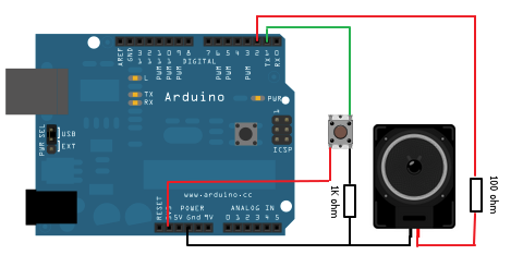
In my case, what worked best: the longest one is shared between the pwm pin and the piezo, the shortest one goes to GND and the middle one goes to the other pin of the piezo. Hi, thanks! I noticed that the autotransformer has 3 different sizes pins. If anyone can find similar transformers on Mouser I'd be interested in seeing it. Also ozitronics posted some data (see picture) on his 'autotransformer' with similar resistance and 91mH/2.1mH inductance. The main principle of the piezo buzzer is. Here is the transformer that I measured: Pin1-2 154ohm and Pin 2-3 8ohm Pins 1-3 is ~161ohm. smart phone At once the Arduino UNO gets the directs of the current location the Arduino transfers the coordinate. The auto-transformer has three leads and you can measure the resistance across the leads to determine which is which. If anyone can explain the phyisics behind its operation, pleas chime in! thanks.
#Safe current for arduino piezo code#
In the code below, the incoming piezo data is compared to a threshold value set by. Without it, the analog pin might not be capable of reading the piezos signal. The placement of the resistor is used to save the piezo from damage from extra current. Having very cursory knowledge of electronics, Im extremely confused by this statement I took from the Arduino Knock example. The black blob is a pulsing square wave that the Arduino can produce. The piezo is attached to analog pin 0 with a 1 Megohm resistor in between the two legs. Im an electronics noob trying to understand this Arduino circuit below. For example, Mide's piezo fan draws about 5mA. High voltage amplifiers will typically have a low output current (<1 A), but piezo actuators require very little current. Simply put, the amplifier’s maximum output current should be greater than the peak current draw of the piezo actuator. an Auto Transformer and a 'black blob' of circuitry. This is the current output of the amplifier. Go to the dollar store and purchase their Intruder Alert noise maker and your'll find. You can get fairly high voltages from a Piezo element, but not much current. Arduino voltage booster (might be totally useful to another project though!).Arduino charge pump to boost the voltage (cool idea though).astable multivibrator as suggested by some piezo MFG. We need to use a relay between Arduinos pin and light bulb to protect Arduino from high voltage/current.

Many forum suggestions exist and I tried all these without success:

there is zero good information on the internet. In industrial settings, IoT sensors can monitor workplace. I want the light to simply blink when the vibration is detected. It is super simple and as loud as your fire alarm. IoT projects ideas can significantly improve safety in various environments. Total Newbie I am trying to use the Arduino Uno with a Piezo Sensor to simply turn a LED light on when the Piezo detects a vibration over a certain threshold and then off right away. Hey all! I struggled with making a loud piezo buzzer from 5volts.


 0 kommentar(er)
